Stormwater Design Example: Pond

POND DESIGN EXAMPLE
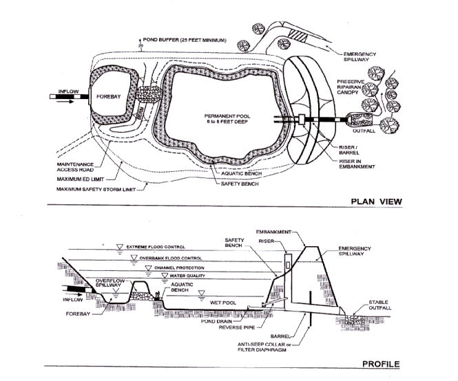
The following design example is for the "wet extended detention (ED) pond," from STP Group 1 (stormwater ponds).
On this site the developer is required to provide control for the following:
![]() Based
on the specific criteria in a region. These criteria may vary. See Sizing
Options.
Based
on the specific criteria in a region. These criteria may vary. See Sizing
Options.
Site Data:
The site area and drainage area to the pond is 38.0 acres. Existing ground at the pond outlet is 320'. Soil boring observations reveal that the seasonally high water table is at elevation 318'. The underlying soils are SC (sandy clay) and are suitable for earthen embankments and to support a wet pond without a liner. The stream invert at the adjacent stream is at elevation 316'. TR-55 analyses results are in Table 1.

Step 1. Compute Design Volumes
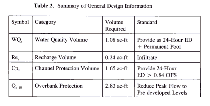
Required volumes for 1-4 were computed under Example 1 of the sizing options section and are presented in Table 2.
Step 2. Investigate potential pond hazard classification
Review downstream conditions and compute a preliminary Breach Peak Discharge (Qmax) per state requirements. Breach discharge and actual classification to be confirmed once embankment design has been finalized.
Qmax = (3.2) (Hw5/2) where,
Hw = depth of water at the dam at the time of failure, in feet. (measured from the emergency spillway (or design high water, if no emergency spillway exists) to the lowest point in the original cross section at the centerline of the dam.
Assume Hw = 12 feet: Qmax = (3.2) (12)5/2 = 1596 cfs
Check downstream culvert/road for passage of this flowrate, by separate analysis (FHWA culvert charts and HY-8 computer program) existing culvert and road section will pass 1596 cfs with only 1.0' of flow over road. No other structures or road crossings for 1.8 miles downstream
Preliminary classification: Class "a": Low Hazard
State requirements vary. For detailed information consult the appropriate state agency.
Step 3. Compute stream channel protection (Cpv) and overbank protection (Qp-10) volume requirements
Cpv was previously computed to require 1.65 ac-ft of storage for 24 hour detention of runoff from the post-developed 1 year storm (see Table 2).
The preliminary Qp-10 was previously computed to require 2.83 ac-ft of storage for attenuation of the post-developed 10 year storm to the pre-developed peak discharge (see Table 2).
Note that at this step the volume for Qp-10 is computed only on a preliminary basis using TR-55 "short-cut" routing method. While the TR-55 short-cut method reports to incorporate multiple stage structures, experience has shown that an additional 10-15% storage is required when multiple levels of extended detention are provided inclusive with the 10 year storm. So, for preliminary sizing purposes add 15% to the required volume for the 10 year storm. Qp-10 = 2.83 * 1.15 = 3.25 ac-ft. The final volume is verified using SCS TR-20 "Project Formulation-Hydrology" computer program.
To complete this step the designer will need to develop the site hydrologic analysis using TR-55 or TR-20 to compute the volume of runoff for the 1 year post-developed storm and peak discharges for the 10 year pre-and post-developed storms (see Example 1, in sizing options section).
Step 4. Water Quality Allocations
The recharge volume must be provide in a separate facility. Assume that 100% of recharge volume (0.24 ac-ft) is provided in an upland bioretention facility. The required water quality volume for this facility is therefore reduced by this amount:
New WQv required in pond: (1.08 ac-ft) - (0.24 ac-ft) = 0.84 ac-ft
Step 5. Pretreatment Volume
Size wet forebay to treat 0.1"/impervious acre. (13.8 ac) (0.1") (1'/12") = 0.12 ac-ft
(volume is included in WQv as part of permanent pool volume)
![]() Specific
treatment volumes may vary, but 0-1"/impervious acre is typical. See Design
Criteria - Ponds
Specific
treatment volumes may vary, but 0-1"/impervious acre is typical. See Design
Criteria - Ponds
Step 6. Allocation of permanent pool volume and ED volume
Size permanent pool volume to contain 50% of new WQv (0.84 ac-ft, see step 4):
� (0.84 ac-ft) = 0.42 ac-ft. (include 0.12 ac-ft as a forebay within this volume)
Size extended detention volume to contain 50% of WQv: (�) (0.84 ac-ft) = 0.42 ac-ft
Note: This design approach assumes that all of the ED volume will be in the pond at once. While this will not be the case, since there is a discharge during the early stages of storms, this conservative approach allows for ED control over a wider range of storms, not just the target rainfall.
Step 7. Conduct pond grading and determine storage available for permanent pool and ED, and compute ED orifice size
This step involves initially grading the pond (establishing contours) and determining the elevation-storage relationship for the pond. Storage must be provided for the permanent pool (including sediment forebays), extended detention (WQv-ED), Cpv-ED, and 10 year storm, plus sufficient additional storage to pass the 100 year storm with minimum freeboard. An elevation-storage table and curve is prepared using the average area method for computing volumes. See Figure 2 for pond grading and Figure 3 for Elevation-Storage Data.
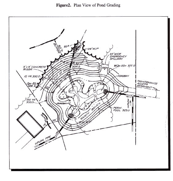

Pond bottom set at elevation 321.0. Provide gravity
flow to allow for pond drain, set riser invert at 320.8 and barrel outlet elevation
at 320.5.
Required permanent pool volume = 0.42 ac-ft.
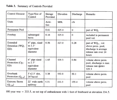
From the elevation-storage table, read elevation 325.0 (0.61 ac-ft > 0.42
ac-ft) OK
Set permanent pool water surface elevation
(wse) = 325.0
Forebay volume provided in two pools with avg. vol. = 0.08 ac-ft each (0.16 ac-ft > 0.12 ac-ft) OK
Required extended detention volume (WQv-ED)=
0.42 ac-ft. From the elevation-storage table, read elevation 327.0 (0.56 ac-ft
> 0.42 ac-ft) OK.
Set ED wse = 327.0
Note: Total storage at elevation 327.0 = 1.17 ac-ft (greater than required WQv of 0.84 ac-ft)
Compute the required WQv-ED orifice
diameter to release 0.56 ac-ft over 24 hours
Average ED release rate = 0.56 ac-ft (43,560
ft2/ac) / (24 hr) (3600 sec/hr) = 0.28 cfs
Average head = (327 - 325.0)/ 2 = 1.0'
Use orifice equation to compute cross-sectional
area and diameter
Q = CA(2gh)�, for h = 1.0
A = 0.28 cfs / [(0.6)((2)32.2'/s2)(1.0'))�]
A = 0.06 ft2, A =d2
/ 4; dia. = 0.27 ft = 3.3" Use 4" pipe with 4" gate valve
QWQv-ED = (0.6) (0.06 ft2)
[(2)(32.2'/s2)�] (h�), Q = (0.29) h�,
where: h = wse - 325.14
Step 8. Compute release rate for Cpv-ED control and establish Cpv elevation
Required Cpv storage = 1.65 ac-ft (see
Table 2). From the elevation-storage table, read elevation 329.3'.
Set Cpv wse = 329.3
Size low flow orifice to release 0.84 cfs @ elev.
329.3 (see Table 2)
@ wse 329.9, WQv-ED orifice releases
0.59 cfs, Cpv-ED orifice release = 0.84 -0.59 = 0.25 cfs
Head = (329.3 - 327.0) = 2.3'
Use orifice equation to compute cross-sectional
area and diameter
Q = CA(2gh)�, for h = 2.3'
A = 0.25 cfs / [(0.6)((2)(32.2'/s2)(2.3'))�]
A = 0.034 ft2, A =d2
/ 4; dia. = 0.21 ft = 2.5" Use 4" pipe with 4" gate valve
QCpv-ED = (0.6) (0.034 ft2)
[(2) (32.2'/s2)�] (h�), QCpv-ED
= (0.16) (h�), where: h = wse - 327.10
Step 9. Calculate Qp (10 year storm ) release rate and water surface elevation
In order to calculate the 10 year release rate and water surface elevation, the designer must set up a stage-storage-discharge relationship for the control structure for each of the low flow release pipes (WQv-ED and Cpv-ED) plus the 10 year storm.
Size to capture 3.25 ac-ft (Table 2). From elevation-storage table (Figure 3), read elevation 331.8.
Size 10 year slot to release 50.4 cfs (Table 1)
at elevation 331.8.
@ wse 331.8, WQv-ED orifice releases
0.75 cfs, Cpv-ED orifice releases 0.35 cfs, therefore; allowable
Qp-10 = 50.4 cfs - (.75 + .35) = 49.3 cfs
Max head = (331.8 - 329.3) = 2.5'
Use weir equation to compute slot length
Q = CLH3/2
L = 49.3 cfs / (3.1) (2.53/2)
= 4.0 ft
Use 5' x 2.5' slot for 10 year release (slot should be slightly larger than needed so as to have the barrel control before slot goes from weir flow to orifice flow)
Check orifice equation cross-sectional area
Q = CA(2gh)�, for h = 1.25'
A = (5) (2.5') = 12.5 ft2
Q = 0.6 (12.5 ft2) [(64.4)
(1.2)]�= 67.3 cfs, > 49.3 cfs use weir equation
Q10 = (3.1) (5') H3/2 , Q10 = (15.5) H3/2, where H = wse - 329.3
Size barrel to release approximately 50.4 cfs at elevation 331.8
Check inlet condition: (use FHWA culvert charts)
Hw = 331.8-320.5 = 11.3 ft
Try 24" diameter RCP, Using FHWA Chart 2,
entrance condition 1
Hw / D = 11.3/2 = 5.65, Discharge
= 51 cfs
Check outlet condition: (use NRCS pipe flow equation--NRCS, 1984)
Q = a [(2gH)/1+km +kpL]�
where: Q = discharge in cfs
a = pipe cross sectional area in ft2
g = acceleration of gravity in ft/sec2
H = head differential (wse - downstream
centerline of pipe or tailwater elev.)
km = coefficient of minor losses
(use 1.0)
kp = pipe friction loss coefficient
(= 5087n2/d4/3, d in ", n is Manning's n)
L = pipe length in ft
H = 331.8 - (320.0 + 1.0) = 10.8'
for 24" RCP, 70 feet long: Q = 3.14 [(64.4)
(10.8) / 1+1+(.0126) (70)]� = 48.8 cfs
48.8 cfs < 51 cfs, use outlet equation
Q = (14.85) H�, where H =
wse - 321.0
Note: pipe will control flow before high stage slot goes from weir flow to orifice flow
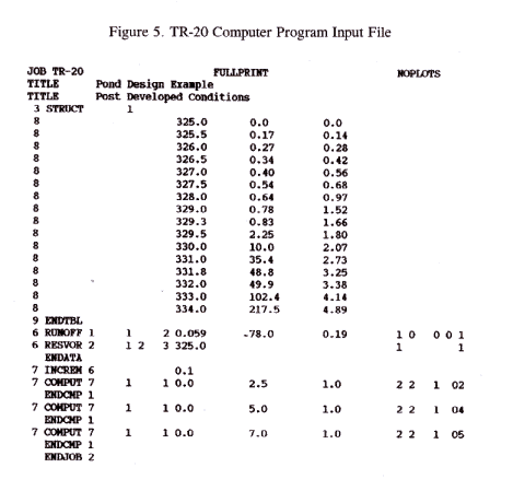
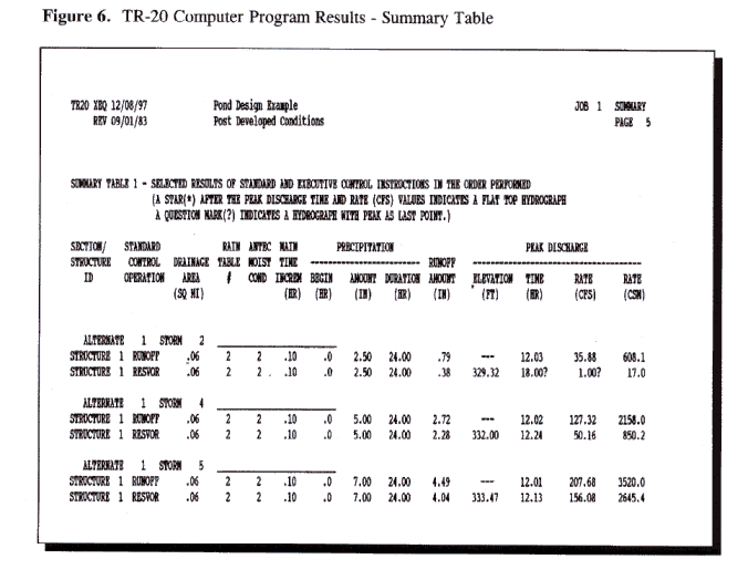
Complete Stage-Storage Discharge Table (Figure 4) up to preliminary 10 Year wse (331.2) androute 10 year post-developed condition inflow using TR-20 (see Figures 5 and 6 for input and summary files from TR-20 run). Note TR-20 routing computes 10 year wse at 332.0 with discharge = 50.1 cfs.

Step 10. Size emergency spillway, calculate 100 year water surface elevation, and set top of embankment elevation
The 10 year wse is at 332.0. Set the emergency spillway at this elevation and use NRCS-Design Data for Earth Spillways (Engineering Field Manual, RTSC-NE-ENG 1110)
Q100 inflow = 216.3 cfs.
Try 22' wide vegetated emergency spillway
with 2:1 side slopes.
@ elevation 334.0, H = 2.0', QES
= 164 cfs. QpS = 53.5 cfs
100 year wse = 333.5, so set top of embankment with 1 foot of freeboard at elevation 334.5.
Check pond classification assumption: Height = 332-320 = 12', equals assumed embankment height, Pond will remain a Low Hazard.
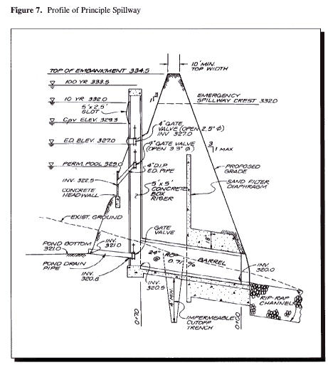
See Figure 7 for profile through principal spillway of the facility.
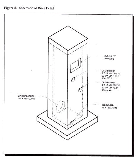
See Figure 8 for a schematic of the riser.
