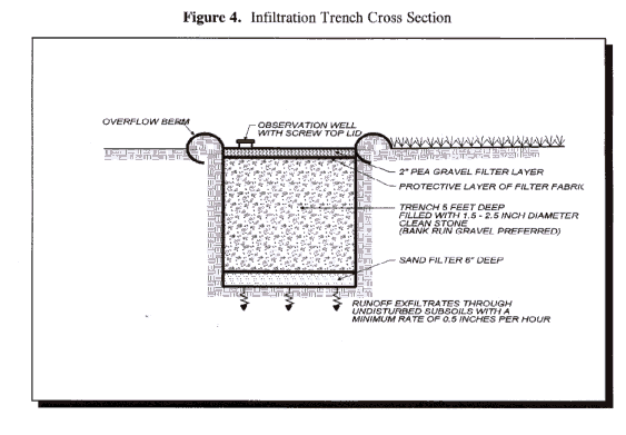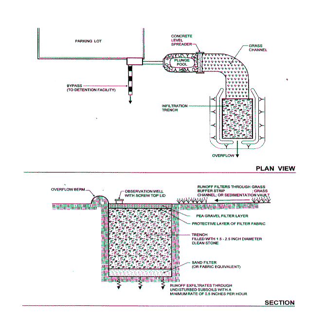
Stormwater Design Example: Infiltration Trench

INFILTRATION TRENCH DESIGN EXAMPLE
This example describes in detail the design of an infiltration trench to treat stormwater runoff from the Brown Community Center (Figure 1). The trench must meet the following design criteria:
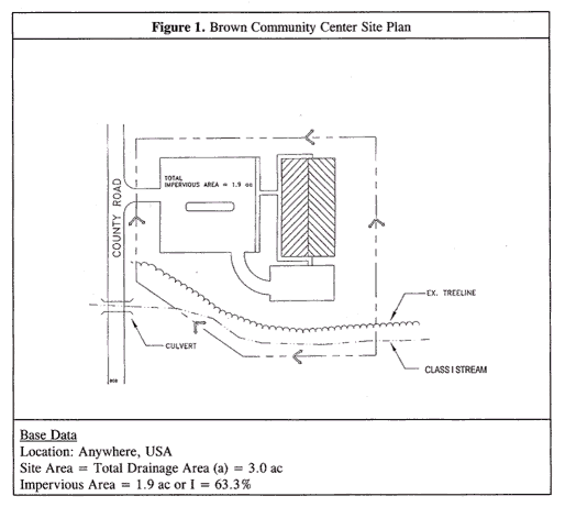
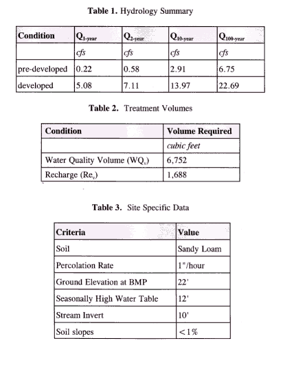
Step 1. Determine if Infiltration Is Feasible
The table below summarizes the requirements that need to be met to successfully implement infiltration practices. On this site, infiltration is feasible, with restrictions on the depth and width of the trench.
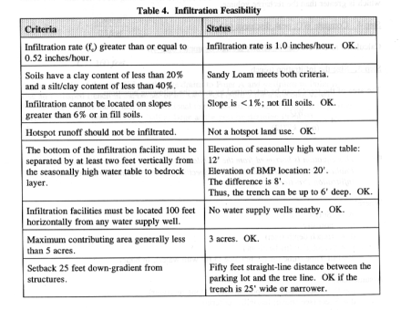
This table presents examples for infiltration feasibility criteria. Specific criteria may vary. See Selection Criteria for more details.
Step 2. Compute Water Quality Volume:
WQv previously determined to be 6,752 cubic feet.
Step 3. Compute Recharge Volume
The recharge volume was previously calculated as 1,688 cubic feet. The infiltration trench will automatically meet the recharge requirement because it infiltrates the entire water quality volume which is greater than the recharge volume.
Step 4. Compute WQv peak discharge (qp)
Calculated as 2.6 cfs (see Sandfilter Design Example, Step 4).
Step 5. Size the infiltration trench.
The area of the trench can be determined by using the following equation:

This equation is borrowed from the Maryland Department of Natural Resources 1984 Publication "Maryland Standards and Specifications for Stormwater Management Infiltration Practices"
Where:
A = Surface Area
n = porosity
d = trench depth (feet)
k = percolation (inches/hour)
T=Fill Time (time for the practice to fill
with water), in hours
Assume that:
n= 0.32 (see Chapter 3; porosity for a stone
reservoir)
d= 5 feet (see above; feasibility criteria)
k= 1 inch/hour (see above; site data)
T= 2 hours
Therefore:

A = 3,800 ft2
Since the width can be no greater than 25' (see above; feasibility), determine the length:
L = 160 feet
Assume that of the runoff from the site drains
to Point A and drains to Point B.
Use an L-shaped trench in the corner of
the site (see Figure 2 for a site plan view).
The surface area of the trench is proportional
to the amount of runoff it drains (e.g., the portion draining from Point A is
half as large as the portion draining Point B).
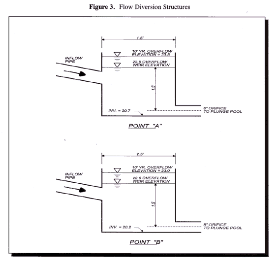
Step 6. Size the flow diversion structures
Since two entrances are used, two flow diversions are needed.
For the entire site:
Q10-year = 13.97 cfs (See site data)
Peak flow for WQv = 2.6 cfs.
(Step 4).
For the first diversion (Point A)
Assume peak flows equal of their value for the entire site.
Thus, Q10-year = 4.7 cfs
Peak flow for WQv = 0.9 cfs
Size the low flow orifice to pass 0.9 cfs with
1.5' of head using the Orifice equation.
Q=CA(2gh) � ; 0.9 cfs = 0.6A(232.2
ft/s2 1.5') �
A=0.15 sq. ft. = d2/4;
d = 5.3"; use 6"
Size the 10-year overflow at 22'. Use a concrete weir to pass the 10-year flow (4.7 cfs.) Assume 1 foot of head to pass this event. Size using the weir equation.
Q = CLH1.5; L= Q/(CH1.5)
L = 3.8 cfs/ (3.1)(1)1.5 = 1.2';
use 1.5'
Size the second diversion (Point B) using the same techniques.
Peak flows equal of their volume for the entire site. Thus:
Q10-year = 9.3 cfs
Peak flow for WQv = 1.7 cfs
Using the same calculations as above, and substituting
the higher flows, d=7.3";
Use 8" for low flow orifice diameter.
For the 10-year overflow, L=2.4'. Use 2.5'.
Step 7. Size pretreatment.
Must treat � of the WQv. Therefore, treat 1,688 ft3.
![]() In
general, infiltration practices should have significant pretreatment volumes
to prevent clogging. (See Design Criteria - Infiltration)
In
general, infiltration practices should have significant pretreatment volumes
to prevent clogging. (See Design Criteria - Infiltration)
For pretreatment use a plunge pool, a grass channel and a pea gravel filter layer with filter fabric.
Pea Gravel Filter
The 2" pea gravel filter layer covers
the entire trench. Assuming a porosity of 0.32, the water quality treatment
in the pea gravel filter layer is:
WQfilter= (0.32)(2")(1 ft/12
inches)(4,000 ft2) = 213 ft3
Plunge Pools
Use a 5'X10' plunge pool at Point A and
a 10'X10' plunge pool at Point B with average depths of 2'.
WQpool= (10 ft)(10+5 ft)(2 ft2)
= 300 ft3
Grass Channel
Thus, the grass channel needs to treat
at least (1,688-213-300)ft3 = 1,175 ft3
Use a Manning's equation nomograph or software to size the swale.
The channel at point A should treat one third of 1,175 ft3 or 392 ft3
V=0.5 ft/s
Therefore, adjust length:
L= (300 ft)(392 ft3/2,250 ft3)
=52 feet. Use 55 feet.
Size the swale at point B using the same method.
Q=1.7 cfs Slope = 0.5%
L=55 feet.
