![]() In
this design example, the NRCS TR-55 method is used as the design methodology.
In
this design example, the NRCS TR-55 method is used as the design methodology.
Design Example No. 2: Commercial Development - Brown Community Center
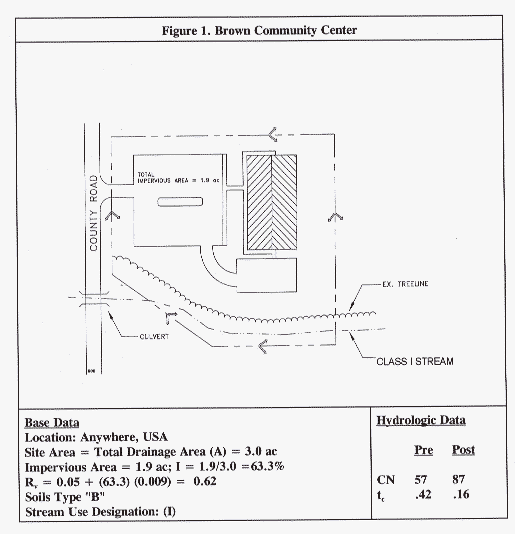
This is a sizing example for a commercial site, Brown Community Center. The layout of the Brown Community Center is shown in Figure 1.
In this design example, the NRCS TR-55 method is used as the design methodology.

Step 1. Compute Water Quality Volume WQv
Criteria:
Step 1a. Compute Runoff Coefficient
This runoff coefficient is derived from Schueler's Simple Method.
Rv = 0.05 + (I) (0.009)
Where:
I = Impervious Cover (%)
Rv = 0.05+(63.3)(0.009) = 0.62
Step 1b. Compute WQv
WQv = (P1) (Rv ) (A)
Where:
P1 = 90% Rainfall Event (Inches). Assume 1" in this example
A = 38.0 acres
WQv = (1.0") (Rv ) (A) / 12
= (1.0") (0.62) (3.0ac) (43560ft2/ac) (1ft/12in)
= 6752 ft3Check Minimum: (0.2) (3.0 ac) (3630) = 2178 ft3 [okay]
Step 2a. Determine Recharge Equation Based on Hydrologic Soil Group (Table 1).
|
Table
1. Recharge Based on Soil Group
|
|
|
Recharge
Requirement
|
|
|
A
|
(0.38)
(Rv) (A) / 12
|
|
B
|
(0.25)
(Rv) (A) / 12
|
|
C
|
(0.13)
(Rv) (A) / 12
|
|
D
|
(0.06)
(Rv) (A) / 12
|
Step 2b. Compute Recharge Volume
For "B" soils, (0.25 inches) (.62) (3.0 ac) (1/12"/ft) (43,560 ft2/ac) = 1,688 cubic feet; this represents the minimum target volume for recharge purposes.
Step 3. Compute Stream Channel Protection Volume (Cpv):
In this design example, we assume that channel protection is not required at this site due to the small site size, and relatively flat slopes in the watershed.
Step 4. Compute Peak Discharge Control Volume (Qp):
Table 2 presents Input Parameters Per attached TR-55 calculations (see Figures 2 and 3).
|
Table
2. Input Parameters for STP Sizing
|
|||||
|
Condition
|
RCN
|
Q
1-year
|
Q
2-year
|
Q10-year
|
Q100-year
|
|
cfs
|
cfs
|
cfs
|
cfs
|
||
|
pre-developed
|
57
|
0.22
|
0.58
|
2.91
|
6.75
|
|
developed
|
83
|
5.08
|
7.11
|
13.97
|
22.69
|
Assume that 10-year quantity peak control is required (Qp10).
Per TR-55, Figure 6-1 (Page 6-2 in TR-55), for a Qin of 13.97 cfs, and an allowable Qout of 2.91 cfs, the Vs necessary for 10-year control is 0.24 ac-ft or 16,890 ft3, under a developed CN of 83.
Step 5. Analyze for Safe Passage of 100 Year Design Storm (Qf):
At final design, prove that discharge conveyance channel is adequate to convey the 100 year event and discharge to receiving waters.
|
Table
3. Summary of Design Information for Brown Community Center
|
|||
|
No.
|
Category
|
Volume
Required
(cubic feet) |
Notes
|
|
1
|
Water
Quality (WQv)
|
6,752
|
|
|
2
|
Recharge
(Rev)
|
1,688
|
This
volume can be included within the WQv storage
|
|
3
|
Stream
Protection (Cpv)
|
n/a
|
Not
required on this site.
|
|
4
|
Peak
Control (Qp)
|
16.890
|
10-year
control
|
|
5
|
Flood
Safe Passage (Qf)
|
Provide
safe passage for the 100-year event in final design
|
|