Stream
Restoration: Flow Deflection/Concentration Practices
The purpose of flow deflection/concentration practices is to change the direction of stream flow or to concentrate stream flow. These structures are predominately used to deflect flow away from eroding stream banks, concentrate the flow in the center of the channel, redirect water in and out of meanders, and/or enhance pool and riffle habitats.
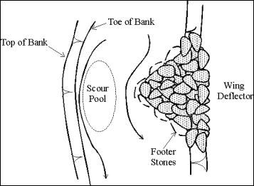
A single wing deflector is a triangular structure that extends out from the streambank into the stream, with the widest portion along the bank and the point extending into the channel. The purpose is to change or (deflect) the direction of stream flow either to narrow and deepen the baseflow channel or to create sinuosity in the channel.� When used to narrow and deepen the baseflow channel they can also promote the formation of overhead cover (undercut banks) on the opposite bank.
Wing deflectors can consist of a rock filled log frame or they can be made entirely of rock.� In urban stream applications they more often consist entirely of rock. Single wing deflectors are not often used in urban applications as they tend to force water toward the opposite bank, and unless the opposite bank is sufficiently stable or armored, bank erosion can ensue. �
They are constructed by first digging two trenches that meet at the apex for installation of the footer stones.� The footer stones should be spaced so that there is about 1/3 of the stone diameter separating them.� This allows the weir stones to interlock when placed on top.� Once the weir stones have been placed to form the two arms of the triangle, the central portion can be back filled with excavated material and large stone placed on top to achieve the desired elevation.
The wing deflector should extend up to the bankfull elevation at the streambank or to the height of the streambank which ever is higher.� The structure grades down to the channel invert about 1/3 of the way across the channel.� However, the distance the deflector extends out into the channel will depend upon the site-specific circumstances of the application (Figure 24).
Figure 24: Plan View of Single Wing Deflector
When two wing deflectors are placed opposite each other they serve to narrow or constrict the flow of water.� The double wing deflector is more often used in urban applications as it forces the water toward the center of the channel and deepens the baseflow channel. Double wing deflectors also create an area of increased velocity between them, enhancing riffle habitat between and just upstream of the structure. This increased velocity also creates an area of scour, creating pool habitat downstream of the structure. The construction is the same as a single wing deflector except that in some instances, a rock sill at the stream invert may connect the two structures (Figures 25 and 26).
Both single and double wing deflectors have significant habitat enhancement potential.� These structures enhance habitat through pool formation, the narrowing and deepening of the baseflow channel, and the enhancement of riffle habitat.
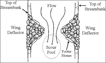
Figure 25: Plan View of Double Wing Deflector

Figure 26: Section View of Double Wing Deflector
Vanes are linear structures that extend out from the streambank into the stream channel in an upstream direction.� They essentially mimic the effect of a tree partially falling into the stream. They are usually placed along the streambank where erosion is occurring along the toe of the slope. The purpose of vanes is to reduce erosion along the streambank by redirecting the stream flow toward the center of the stream.� In addition, they tend to create scour pools on the downstream side.� Vanes can be made of rock or log.� They grade down from the bankfull elevation at the streambank to the channel invert at their terminus in the stream. Vanes generally extend out from the stream bank 1/3 of the bankfull width and are angled upstream from the bank at a 20 to 30 degree angle.� They should be carefully located and installed so as not to produce additional erosion on the upstream side where they meet the bank (eddy scour) or allow flows to outflank them, exacerbating existing bank erosion problems. The only difference between the log vane and the rock vane is the material used. The J - vane is basically the same as a rock vane with the exception that it curls around at the end in the shape of a �J.�� The curved end portion serves to enhance downstream scour pool formation (Figures 27 - 29).
The rock vane is constructed by first excavating a trench for the footer stones.� The footer stones are then placed in the trench so that there is a gap between them equal to��� 1/3 of the stone diameter.� This gap will allow the vane stones to interlock with the footer stones.� The vane stones should be placed on top of the footer stones so they are staggered over two adjacent footer stones and skewed slightly upstream of the footer stones. As the vane is built out and slopes down from the bank, footer stones will become unnecessary when the vane stones can be placed in the trench and extend up to achieve the desired elevation.
Rock, log and J-vanes have significant habitat enhancement potential through the creation of downstream scour pools, narrowing and deepening of the baseflow channel, and the enhancement of riffle habitat along the upstream side.
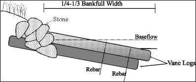
Figure 27: Section View of Log Vane

Figure 28: Section View of Rock Vane

Figure 29: Plan View of Rock Vane and J-Rock Vane
Cut-off sills are low rock sills similar to a linear deflector and often used in conjunction with linear deflectors.� They extend out from the streambank into the stream channel at an angle of 20 to 30 degrees from the bank in an upstream direction.� They can either intersect with a linear deflector or terminate at the baseflow channel.� The purpose of a cut-off sill is to promote deposition and bar formation along the edge of a channel in order to narrow and better define the baseflow channel.� They do not extend above bankfull height and are usually much below it.� They are also used to stabilize existing bars.� In such instances they are installed in the existing bar and extend only slightly above it (Figures 30 and 31).
Cut-off sills have a modest potential to enhance stream habitat.� When utilized in channels with shifting baseflow channels and high bedload movement they can be very effective at stabilizing lateral bars and better defining the baseflow channel.�
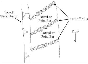
Figure 30: Plan View of Cut-Off Sill
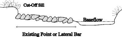
Figure 31: Section View of Cut-Off Sill
A linear deflector is simply a line of boulders placed within the stream channel rather than along the bank.� The purpose of this structure is to narrow, deepen and better define the base flow channel.� The top of the deflector generally does not extend above the bankfull elevation and is usually much below it.� The area between the deflector and the stream bank either is back filled with materials excavated during the installation, imported stone/fill, or allowed to naturally sediment in (Figure 32).��
Placement of a linear deflector must take into consideration the condition of the opposite stream bank.� If the opposite bank is potentially unstable, bank stabilization measures may be necessary.� If the opposite bank is unstable and left untreated, there is the potential for bank erosion and channel widening.� Linear deflectors are most often used in stream channels that are overly wide, have shallow or shifting base flow channels and high bed load sediment movement.
Linear deflectors have a significant potential to enhance stream habitat in streams with shallow, poorly defined baseflow channels.� By better defining and deepening the baseflow channel, linear deflectors improve fish passage and expand the total amount of habitat available for fish.
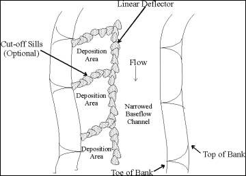
Figure 32: Plan View of Linear Deflector